What the tool knows about the .xcs file format, where each rule is written down, and how to
check a generated file against the real thing. Everything here targets the xTool F2 on the VANTAGE-ALPHA
baseline.
When a feature is not explicitly documented in xcsformat.md, do not guess the JSON.
XCSViewer.md §3 makes this a mandatory protocol:
.xcs sample from xTool Creative Space that demonstrates it.xcsformat.md updated with verified facts.Triggers that call for a sample: new shape types (polygons, stars, bezier curves), new processing modes such as 3D relief, bitmap filters and image adjustments, and grouping or nesting of objects.
XCS separates an object's origin from its geometric data. Path coordinates are relative to the object's own
top-left; the bed position lives only in x and y. Set both to absolute machine
coordinates and XCS applies the offset twice, which drops the shape far outside the work area or onto 0,0.
wrong   dPath "M 50 50 …"   x: 50   y: 50   → drawn 50mm from an anchor at 50,50
right   dPath "M  0  0 …"   x: 50   y: 50   → drawn at 50,50
Generate technical paths centred on (width/2, height/2), then set x and
y to the top-left position you want. offsetX/offsetY carry the
distance from that anchor to the geometric centre. Documented in xcsformat.md §13.
| Rule | Value |
|---|---|
| Working surface | 0,0 to 100,100 mm |
| Default centre | 50,50 mm — every generated pattern |
| Coordinates | mm from top-left |
| Fill processing | COLOR_FILL_ENGRAVE, reached through isFill: true |
| Path processing | VECTOR_ENGRAVING, reached through isFill: false |
Never hardcode a processing-type string in a pattern component — use the isFill
abstraction and let the exporter choose. From GEMINI.md §1 and §4.
Geometry is joined to its laser settings by matching GUIDs, and a file that breaks the join opens without settings. Two structural tests every export must pass:
canvasId must exist as a key in device.data.value
and match the id of the corresponding entry in canvas[].canvas[n].displays[] must exist as a key in
device.data.value[n][1].displays.value.
Plus the boilerplate: 36-character UUIDs, every layerColor present in
canvas.layerData, every Map wrapped as {"dataType":"Map","value":[…]}, all four
operation nodes per shape, and root metadata extId: "GS006" / extName: "F2".
xcsformat.md §2, §6, §7.
XCS anchors text at the left edge of the baseline and glyphs grow up from it, so a label placed at the bottom of a grid overlaps the grid rather than sitting under it.
| Scenario | Anchor | Grows |
|---|---|---|
| Horizontal, 0° | Left-edge baseline | Right (+X) |
| Vertical, −90° | Top-edge baseline | Down (+Y) |
| Centre horizontally | targetX − width/2 | — |
| Centre vertically | targetY + width/2 | — |
Text also has to be baked: a TEXT object carries charJSONs, one PATH per
character, and fontData with metrics and glyph paths. Without them the text is invisible to
F2 offline processing. xcsformat.md §4, §11, §12 and XCSViewer.md §5.
xcs-system.js is the only module permitted to generate and manage formal XCS structures. It
handles text baking, node boilerplate and the conversion to the left-baseline anchor.
XCSExporter and XCSIR are thin compatibility bridges over it.
XCSViewer.md §2.
| Property | Internal | Formal XCS |
|---|---|---|
| Coordinates | mm from top-left | factor in scale and offsetX/Y |
| Dimensions | w, h in mm, final size | width, height, may be unscaled |
| Text anchor | centre or baseline | left-edge baseline, strict |
| Colours | hex, #5b9bd5 | lineColor decimal, fillColor hex |
Gaps found by exporting every Shape Fill style to XCS and reading what came out. The canvas preview and the engraved result are not the same picture, and these are the reasons why.
The canvas hides whatever a later shape paints over. The recorder does not — every
fill() and stroke() becomes a shape in the file, including the parts no one will
ever see. Nothing removes them afterwards.
| Style | Shapes | Fully buried | Partly buried | Engraved mm² | Visible mm² | Wasted |
|---|---|---|---|---|---|---|
| Gears | 4,320 | 1,223 — 28% | 2,206 | 9,490 | 1,979 | 79% |
| World Coins | 6,358 | 2,518 — 40% | 1,302 | 10,441 | 2,450 | 77% |
| Buttons | 2,000 | 267 — 13% | 1,186 | 8,721 | 2,219 | 75% |
| Pipes and Gears | 971 | 91 — 9% | 560 | 5,511 | 1,666 | 70% |
| Rows of Ducks | 1,755 | 411 — 23% | 1,160 | 6,263 | 2,422 | 61% |
| Circuit Board | 611 | 64 — 10% | 455 | 2,056 | 905 | 56% |
| Painted Lady | 1,375 | 350 — 25% | 809 | 4,300 | 2,008 | 53% |
| Gems | 2,194 | 82 — 4% | 1,944 | 2,327 | 1,127 | 52% |
| 3D Glossy | 498 | 0 | 422 | 2,473 | 1,196 | 52% |
| 3D Basic | 416 | 0 | 329 | 2,420 | 1,215 | 50% |
| Autumn Leaves | 1,475 | 116 — 8% | 1,040 | 2,940 | 1,558 | 47% |
| Flat | 225 | 2 — 1% | 150 | 2,097 | 1,197 | 43% |
| Christmas Cookies | 871 | 75 — 9% | 391 | 2,553 | 1,585 | 38% |
| Jigsaw, Solved | 649 | 0 | 616 | 2,875 | 2,256 | 22% |
Two costs. Burn time is spent on invisible geometry, and where a hidden shape and the shape above it are on different layers, that area is engraved twice at two different powers. Gears engraves 8,929 mm² to show 1,923.
Both kinds are worth removing. Whole shapes disappear in quantity — 2,518 of World Coins' 6,358, 1,223 of Gears' 4,320 — and those can simply be deleted. But they are never the bulk of the waste: partial burial is what every style is full of, and three styles have no wholly hidden shape at all while still wasting half their engraving. Subtraction is the operation that covers both, and culling falls out of it as the case where nothing is left.
Jigsaw's solved fit is the closest thing to a control, and even there 22% is wasted: the pieces tile without overlapping, but each piece's outline covers its own fill.
Needed: occlusion culling before export, or boolean subtraction of covered regions. Neither exists.
Measured, on real designs. tools/occlude-check.mjs runs the pass over an exported
style and checks the one thing that must not move: the binary ink mask before against after. Anything
removed was invisible, so a difference there is a bug rather than a trade-off.
| Style | Shapes | Wholly covered | Trimmed | Engraved mm² | Picture moved | Occlusion time |
|---|---|---|---|---|---|---|
| Gears | 4,122 | 1,060 | 2,501 | 8,788 → 1,929 | 0.009% | 26.7 s |
| World Coins | 6,194 | 2,143 | 3,155 | 9,547 → 2,375 | 0.004% | 5.9 s |
| Flat | 235 | 0 | 193 | 1,926 → 1,192 | 0.046% | 0.05 s |
In every case the engraved area after the pass equals the visible area measured independently by the stencil — 1,929 against 1,929 for Gears, 2,375 against 2,375 for World Coins. Two separate methods arriving at the same number is the strongest check available short of the machine.
It is too slow to run on a slider drag, and that is a placement decision rather than a blocker. Gears takes 26.7 s and World Coins 5.9 s. Gears is the slower despite having fewer shapes because its capsule strokes carry far more points each. The pass belongs in the debounced XCS project build, not in the canvas render loop.
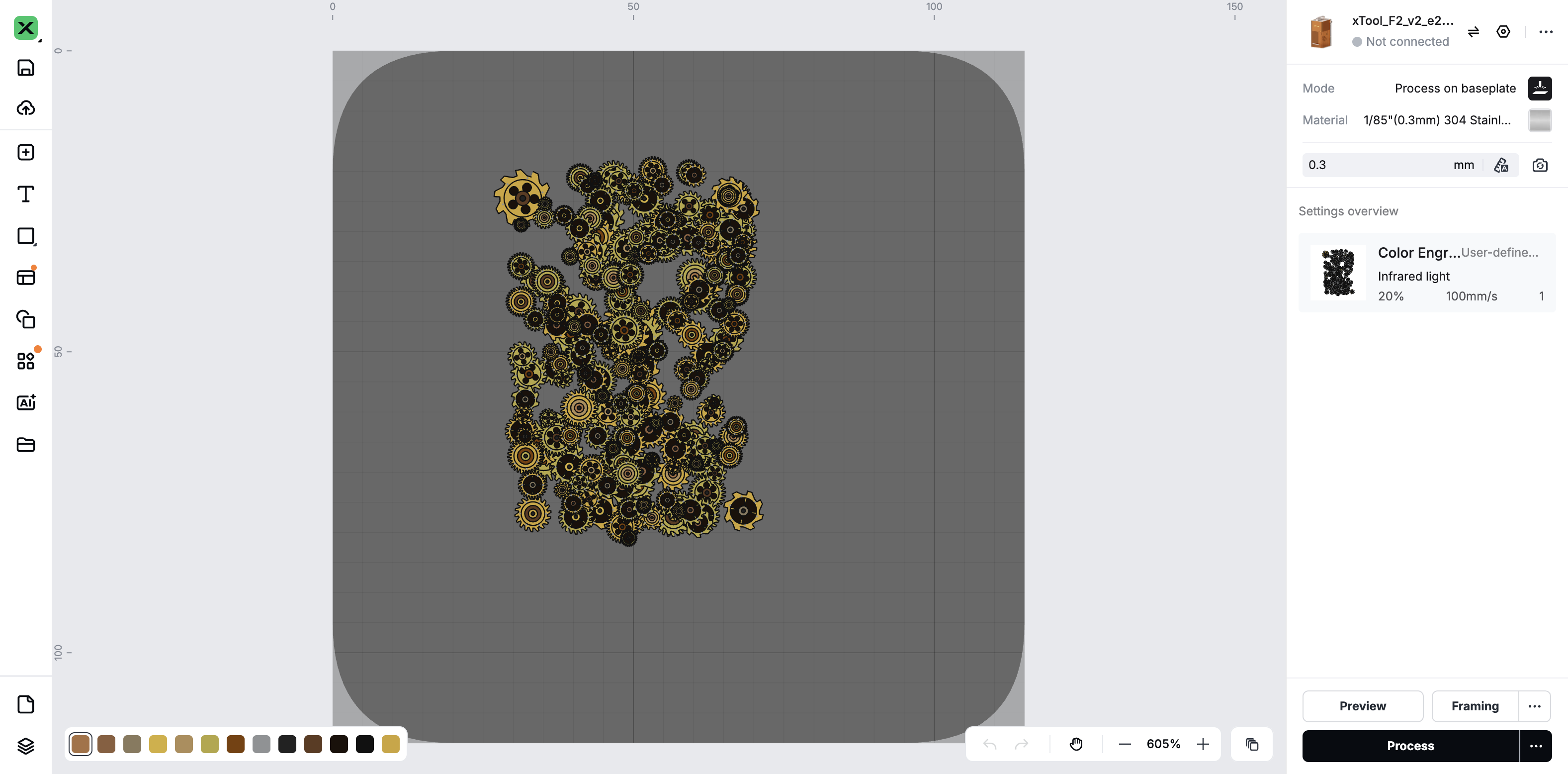
Studio copes at full volume. A real flattened Gears — 3,062 shapes, 1,664 of them carrying holes, 16.4 MB against 36.9 MB unflattened — opens, renders every gear's teeth and interior rings, and screenshots in 201 ms. See the capture. The nine-shape round trip below proved the representation; this proves it at the volume a real design reaches.
The approach is viable. Subtraction produces geometry this file has never asked Studio to draw, so
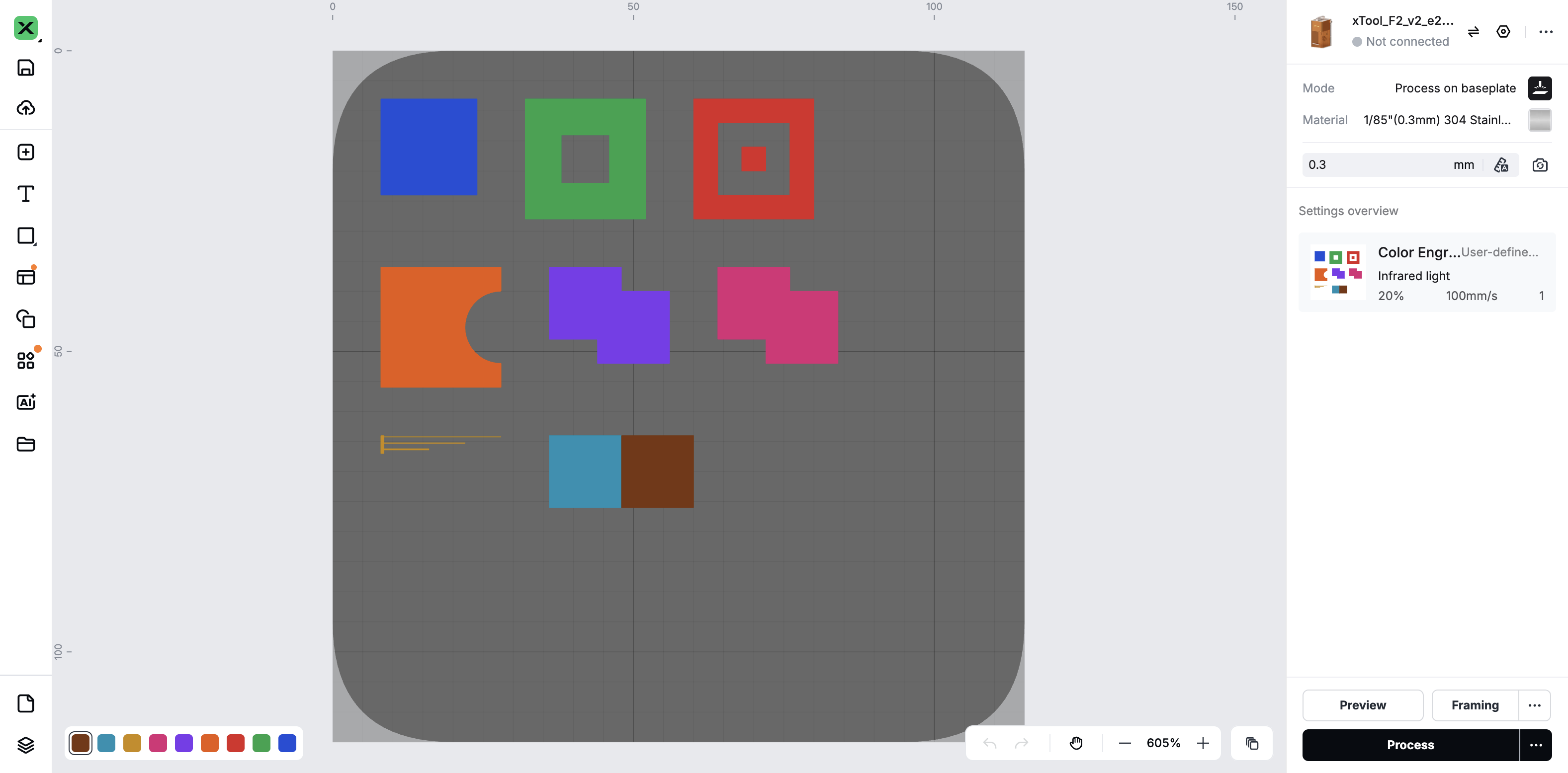
the buried-geometry render test hand-authors each outcome and puts it through the round trip
before any of it is built. Studio drew all nine elements within 0.4 mm of where the file put them and
answered all eleven probes correctly: a hole stayed a hole, a hole with an island inside it kept both, a
concave remainder kept its bite rather than being convex-hulled, and two colours meeting on an exactly
shared edge met with no gap. Compound paths with evenodd are therefore a sound representation
for occlusion. Run 2026-09-16 against Studio 1.5.8; see
the capture.
Two things the round trip cannot settle. A merged shape and the two overlapping shapes it replaces render identically, so no picture will ever show whether merging happened — the overlap that engraves twice is visible only on the part. And Studio draws a 0.05 mm sliver quite happily, which says nothing about whether the F2 engraves it; the threshold below which a boolean remainder should be discarded is a number for the machine, not for the screen.
Measured by xcs-module/tools/buried.mjs on 2026-09-16, Pendant preset, margin 0, at 4,096 px across the bed — 0.0244 mm per pixel, finer than the beam. The tool walks from the topmost shape down, keeping a bitmap of what the shapes above have covered, and paints each shape alone inside its own bounding box: the pixels it covers are the area it started with, and the ones not already in the bitmap are what stays visible. Cross-checked against exact polygon subtraction in tools/occlude-check.mjs, which finds 1,083 wholly covered shapes in Gears where this finds 1,223 — the two differ by the raster resolution and the seed, not by method.
Two earlier counts of this section were wrong in opposite directions and are worth recording. The first used bounding boxes and reported Gears at 94% fully buried; a box inside another box is not covered geometry, so that was an upper bound. The second encoded each shape's index as a colour, painted them in order, and counted the pixels each index still owned — it reported 6. Consecutive indices differ by one in the blue channel, so an antialiased edge between a shape and the shape covering it blends to a colour that is still a valid index, and buried shapes were handed phantom edge pixels. That run's own blend detection reported 0.0%, because no blend ever looked invalid. Exact polygon subtraction is what caught it.
Every distinct flattened colour becomes its own layer with its own parameter block. The 3D shading in these
styles generates shades that never passed through mapPaletteToLaser, so the count is not bounded
by the palette.
| Style | Layers in the exported file |
|---|---|
| World Coins | 51 |
| Circuit Board | 38 |
| Autumn Leaves | 37 |
| Buttons | 26 |
| Jigsaw | 7 |
XCS_LAYERS in constants.js lists eight. The viewer's shape list looks a colour up
in it and simply omits the L1…L8 tag when it is not found, so a 51-layer
export degrades quietly rather than failing.
Unknown: whether XCS Studio or the F2 accepts 51 parameter blocks at all. Untested, and the no-speculation rule applies — this needs an exported sample with many layers before we guess. Needed either way: quantise colours to the laser palette before emitting layers.
Fixed at the source. The generator always picked its base colours from the palette; the draw
functions then invented more — 33 shadeColor() tints computed as arbitrary multiples,
100 hard-coded hex literals, 37 alpha washes whose composited result depended on what lay beneath, and six
arrays of literal colours including the resistor colour codes. None of them had passed through the palette.
Rather than correcting colours after the fact, the drawing is now bound to the palette at the point a
colour is chosen: paletteNear() returns the palette entry closest to a colour, and
shadeColor() keeps its old signature but walks the palette ordered by luminance instead of
multiplying channels, so above 1 lightens and below 1 darkens by steps that exist. Twelve different
near-blacks collapsed to one OUTLINE constant, because the rule is the palette plus black,
singular. Both canvases draw the same thing because both are handed the same thing.
| Style | Palette | Layers before | Layers now |
|---|---|---|---|
| World Coins | 9 | ~400 | 9 |
| Gems | 7 | 85 | 7 |
| Buttons | 9 | 46 | 9 |
| Circuit Board | 5 | 44 | 7 |
| Autumn Leaves | 8 | 29 | 10 |
| Painted Lady | 10 | 23 | 15 |
| Christmas Cookies | 7 | 16 | 8 |
| Gears | 9 | 13 | 10 |
| Pipes and Gears | 9 | 12 | 11 |
A style that matches its palette exactly is drawing only what it was given. The few that sit one to four layers over still have a colour leaking in from somewhere — Painted Lady is the worst at 15 against 11 — and each is a named variable to chase rather than a structural problem.
patterns.md requires a thinning or resolution guard above 2,000 shapes. Gears exports
4,434 — 2.2× over — at 40.7 MB. Jigsaw
caps itself at 1,800 pieces, but it is the only style that does.
| Style | Shapes | File |
|---|---|---|
| Gears | 4,434 | 40.7 MB |
| Autumn Leaves | 1,409 | 4.9 MB |
| Painted Lady | 1,240 | 5.3 MB |
| Jigsaw | 651 | 4.6 MB |
The recorder speaks M L Q ARC ELLIPSE RECT Z. There is no cubic bezier, so every curve is
flattened to a polyline before it reaches the file — the main reason a 4,434-shape export is 40 MB.
Bezier curves are explicitly on XCSViewer.md's ask-for-a-sample list, so emitting C is blocked
until a sample from Creative Space proves the structure.
| Gap | Effect | Kind |
|---|---|---|
clip() content dropped |
Anything drawn inside a clip is skipped: button marbling, gourd rib and wart texture. Silhouettes and base colours survive. | sample |
fillText() dropped |
Coin denominations and years, resistor codes (104K, K5%) never engrave. Glyph baking exists for real TEXT objects but is not wired into the recorder. |
build |
calculatePathLength ignores C, A, H, V |
Measures M L Q Z only, so any path built from other commands reports a short or zero run length and time estimates are wrong. |
build |
calculatePathBBox counts control points |
Walks every coordinate pair, including bezier handles that sit outside the curve, so a shape's reported box is larger than its outline. | build |
| No alpha | xcs-canvas.js never reads it; every shape renders opaque. Translucent fills are composited against the backdrop at record time, which matches visually but cannot represent real transparency. |
sample |
| One stroke width for the whole design | XCS draws paths as hairlines, so strokes become filled capsules at a single physical Outline Width. Per-shape line weights in the artwork are lost. | build |
| Grouping and nesting | Undocumented in xcsformat.md and on the ask-for-a-sample list. Every shape is emitted flat. |
sample |
Measured on the Pendant preset at default settings, one style per run, seeds pinned so the comparison is like for like.
Worked plans for closing the gaps above. Each carries the change, how to get there from here, what could go wrong, and how it will be proved.
The rule. Nothing counts as verified until a real .xcs has been opened in xTool
Creative Space and matched against what our renderer drew. Every refinement in the plans below gets a
test here first, and the test ships with an export button.
our renderer = Creative Space = the machine
This plan comes first because it is the instrument for the other three. Without it, each of them is a claim.
XCS Module Validation runs 16 checks in a single ungrouped list: PROJECT Init, TEXT Baking, RECT / SCORE, CIRCLE / ENGRAVE, BITMAP / COLOR, IMAGE Passthrough, Closed Filled Path, OPEN PATH (Spiral), Compound Vectors, Compound (Reversed), Boundary Frame, Capsule Stroke, Arc Sampling, Color Fidelity, Scale Stress and RUNTIME CRASH.
7 of those already measure rendered geometry rather than structure.
verifyGeometry() reads the rendered SVG's own getBBox() and compares it against
expected millimetres, at a 0.3 mm tolerance, for CLOSED_PATH, SPIRAL, COMPOUND, COMPOUND_REV, FRAME,
CAPSULE_STROKE and ARC_SAMPLE. Its comment records why it exists: structural assertions like
!!dPath never caught the double-translate placement bug, because
_renderPath() applies its own translate on top of whatever dPath it is given.
Three round-trip exports exist already — Test Export (PNG + XCS), Test Export (Stress) for the 1000-item project, and Text Cal Export. They are buttons a person remembers to press, not tests with a recorded expected result.
.xcs for Creative Space.verifyGeometry() checks, moved across intact. They are the baseline every later entry is
measured against, and moving rather than rewriting them keeps that baseline honest.| # | Entry | Draws | Passes when | Round trip confirms |
|---|---|---|---|---|
| 0 | Geometry Baseline | The seven existing shapes | Every getBBox() within 0.3 mm of expected |
Shapes land where the viewer says. Already the de facto baseline. |
| 1 | Layer Budget | A field in 1, 4 and N colours plus outlines | layerData holds exactly colours + 1, and every shape's colour is in that set |
Creative Space lists that many layers, with the powers we intended. |
| 2 | Stroke Width Ladder | Lines at 0.05, 0.1, 0.2, 0.5, 1 and 2 mm | Each exported capsule measures its nominal width | The ladder is visibly six different weights, and says which ones the beam actually resolves. |
| 3 | Overlap and Occlusion | Stacked opaque shapes, fully and partly covered | Shape count matches the culling policy once one exists | Whether a buried shape burns. The one test that cannot be answered off the machine. |
| 4 | Text Fidelity | Baked text at 2, 4, 8 and 16 mm | Glyph paths present, advances correct, anchored left-baseline | The smallest legible size. Extends the existing Text Cal Export into a test. |
| 5 | Curve Fidelity | Circles, arcs and a jigsaw connector at several radii | Sampled polyline stays within tolerance of the true curve | Where sampling starts to show as faceting on the engraving. |
| 6 | Translucency and Clip | Layered translucent fills; a clipped texture | Flattened colour matches the composite; clipped content accounted for | Whether either concept survives at all — this is the sample the no-speculation rule wants. |
| 7 | Style Parity | Each Shape Fill style, canvas against XCS | Raster difference within that style's recorded tolerance | The migration gate. One entry per style, each carrying its own number. |
| 8 | Budget and Scale | Progressively denser fields | Shape count and file size stay inside the declared budget | Where Creative Space or the F2 starts to struggle. Extends Test Export (Stress). |
The three export buttons today produce a file and nothing else. Each render entry should instead carry a short result log — date, XCS version, what was observed, pass or fail — stored beside the test so the answer survives the person who ran it. That is the gap between manual-test-loop.md as a procedure and as evidence, and it is the same gap exportpatches.md is filling by hand for the export format.
manual-test-loop.md?The problem. The HTML canvas clips drawing at its own edge. The recorder has no edge to clip against, so everything a style scatters past the canvas is exported anyway — landing off the machine bed and changing where the rest of the design sits. gears exports 135 × 152 mm onto a 100 × 100 mm bed
Where it stands. Squaring the canvas to 1200 × 1200 px — the bed itself — and
centring each composition on 50,50 closed this. Measured from the exported displays,
Pendant preset, margin 0, on 2026-09-16, every style lands well inside the bed.
gears 28.6–70.6 × 15.6–83.2 mm · coins 28.4–71.5 × 15.9–83.3 mm · autumn leaves 28.5–70.4 × 16.5–83.8 mm · jigsaw 31.5–68.5 × 18.9–81.1 mm
That measurement covers the Pendant preset at margin 0. A preset whose hull reaches further, or a negative margin, is not covered by it and can still push past the edge.
Rendering Gears both ways and diffing the two rasters gave 67% of pixels differing, which is far too much for the “something looks slightly off” it started as. Registering the two images by their ink showed why: the canvas render is 4:3 and the XCS render is square, and both are full of ink to the very edge. The XCS view is not a worse drawing of the same design — it is a different crop of a larger one.
The canvas is 1200 × 900 px, which at PX_TO_MM is 100 × 75 mm. Measured extents
of what actually gets exported:
| Style | Exported extent | Size |
|---|---|---|
| Gears | x −17.5 … 117.5, y −25.8 … 125.8 | 135 × 152 mm |
| World Coins | x −28.1 … 128.1, y −46.2 … 146.2 | 156 × 192 mm |
| Jigsaw | x 31.1 … 68.8, y 18.6 … 81.3 | 38 × 63 mm |
| Pipes and Gears | x 30.8 … 69.2, y 18.4 … 81.6 | 38 × 63 mm |
Counting shapes against the bed separates the styles that scatter from the styles that fill:
| Style | Shapes | On the bed | Straddling | Entirely off |
|---|---|---|---|---|
| World Coins | 260 | 43% | 17% | 39% |
| Christmas Cookies | 63 | 33% | 33% | 33% |
| Buttons | 64 | 55% | 45% | 0% |
| Gems | 161 | 68% | 32% | 0% |
| Autumn Leaves | 1,409 | 87% | 12% | 1% |
| Gears | 4,434 | 94% | 5% | 1% |
| Rows of Ducks | 92 | 100% | — | — |
| Jigsaw | 651 | 100% | — | — |
A third of World Coins is entirely off the bed. It cannot engrave, and it was never visible in the
preview that approved it. Gears loses only 6%, but that 6% is enough to move the ink bounding box from
100 × 75 mm to 135 × 152 mm — and since centerOffsetX/Y centres that
box on 50,50, the whole design shifts. That is the visible difference, not the shading.
Three answers, and they are not equivalent. This is the approval this plan is asking for.
| Option | What it means | |
|---|---|---|
| A | Clip to the canvas | Treat the canvas rectangle as the design surface and clip every shape to it, the way the preview already does. Parity by construction, and nothing can land off the bed. Costs real polygon clipping — flatten each straddling shape and run Sutherland–Hodgman against the rectangle. Changes the output of six styles. |
| B | Scale to fit | Keep every shape and shrink the whole design until it fits the bed. Nothing is lost, no clipping code is needed. But the engraved size stops matching what the size sliders imply, and a style that scatters far shrinks the part you actually care about. |
| C | Centre on the canvas, keep the overflow | Compute centerOffset from the canvas rectangle rather than the ink bounding box. One
line. It fixes the framing, so the XCS view shows what the preview shows — but shapes outside the
canvas still export and still sit off the bed, silently. |
Recommendation: A, with C as the same change's first half. The preview is already drawing the honest picture; the exporter is the thing that disagrees with it. B hides a real problem by making everything smaller, and C alone leaves content off the bed where nobody looks.
Engraved text and clipped texture are the detail the recorder cannot carry, and neither is a decision to take by default. The Shape Fill panel's Detail the Export Drops section turns each one off at the canvas: on, the canvas draws it and the export omits it, so the two renders genuinely differ; off, neither draws it and they agree on its absence. Both default to on, so nothing changes until the question is settled.
| Toggle | What it covers | Measured effect |
|---|---|---|
| Engraved Text | World Coins denominations and years, Circuit Board resistor codes | World Coins, same page load: 3.62% of canvas pixels change and ΔL moves from −4.28 to −2.83, taking the style inside the antialiasing floor. |
| Clipped Texture | Buttons marbling, Autumn Leaves gourd ribs and warts | Buttons, same page load: 3.71% of pixels change while ΔL moves 0.08 — the marbling lightens and darkens in equal measure, so mean luminance alone cannot see it. |
centerOffsetX/Y on the canvas rectangle rather than the recorded ink bounds. On its
own this makes the XCS view frame the design the way the canvas does.The rule, for every style. A generated file carries one layer per colour actually in play, plus one black layer for outlines. Nothing else. This holds for Gears, Coins, Circuit Board and the rest exactly as it holds for Jigsaw. layers = colours in play + 1
Palette-bounded layers were always the intention. A laser engraves a fixed set of powers, the palette is that set, and a file that asks for more colours than the palette holds is asking for something the machine cannot do. The true-colour path — every shade the draw code invents becoming its own layer — was drift, not a decision, and it went unnoticed for a long time. This plan is the correction, and it applies to all fourteen styles.
Every distinct colour the recorder sees becomes a layer, and the draw code emits far more colours than the palette holds. Jigsaw is quoted first only because its extras are few enough to count by eye; the arithmetic and the fix are the same for every style:
| Piece Colors | Layers today | Breakdown |
|---|---|---|
| 1 | 4 | 1 palette + #15171a board + #3a3f45 board edge + #141414 outline |
| 4 | 7 | 4 palette + the same three |
| 9 | 12 | 9 palette + the same three |
The illustrated styles are far worse, because their shading generates colours that never passed through the palette at all:
| Style | Layers | From the palette | Generated |
|---|---|---|---|
| World Coins | 51 | 1 | 50 |
| Circuit Board | 38 | 2 | 36 |
| Autumn Leaves | 37 | 4 | 33 |
| Gears | 14 | 9 | 5 |
Choosing a real laser palette instead of True Color does not reduce this. Measured across seven
styles, the layer count is identical either way — Coins is 51 both times.
mapPaletteToLaser runs once, over the decorative palette, before any drawing happens.
Everything invented after that point escapes it entirely, so the leak is downstream of the mapping in
every style. That is why the fix has to sit at the point colours become shapes, not at the point the
palette is chosen.
Three sources, in order of how much they contribute:
shadeColor() lightens and darkens a palette colour for 3D
relief, and each result is a new colour. Translucent highlights add more, since
flattenColor() composites them against whatever is behind and emits the composite.mapPaletteToLaser.drawBase() fills and strokes the shape outline in a per-style colour,
adding two layers that are backdrop rather than pattern.
Quantise at the single choke point rather than in fourteen styles' worth of draw code.
RecordingCtx._emit is the only place a colour becomes a shape, and
buildXCSProject is the only place shapes become layers.
_emit already knows isThickStroke. Record it on the
shape so outlines are separable from fills.currentColorPool
— the exact subset pickColorSubset chose, already mapped through
resolveRenderPalette to real laser entries. That is the N.buildXCSProject refuses to hand back a project whose
layer count is not N + 1.Layer Mode control offering
Palette and Every colour, defaulting to Every colour, so nothing changes on the first
deploy and both outputs can be exported from the same design and compared..rnr can still reproduce its original export.colorDistance2 is a plain squared
RGB distance, which misjudges dark and saturated pairs. Two shades a viewer reads as different can snap to
one entry while two they read as the same split across two.pathPlanning: "custom". Merging colours changes which shapes share a layer and therefore the
order they burn in..rnr will not produce the same file.Object.keys(canvas.layerData).length === N + 1.layerColor is either in the allowed set or is
the outline black — a set-membership test, not a count, so a merge that loses a colour is caught.xcsformat.md §6 after the merge, since
rewriting a shape's layer touches layerData and the device map together.The rule. Switching Render Target changes how a design is stored, never what it looks like. Anything the canvas draws reaches the XCS project, or the canvas stops drawing it. canvas draw operations = XCS shapes
Counting what the canvas is asked to draw against what the recorder emits, same seed, Pendant preset, default settings:
| Style | Canvas ops | XCS shapes | Lost | Why |
|---|---|---|---|---|
| Autumn Leaves | 1,976 | 1,409 | 567 — 29% | all clipped |
| Buttons | 79 | 64 | 15 — 19% | clipped; 43 more flattened from translucent |
| World Coins | 260 | 260 | 0 | but 62 text draws dropped |
| Circuit Board | 693 | 693 | 0 | but 31 text draws dropped |
| Gears | 4,434 | 4,434 | 0 | — |
| Jigsaw | 651 | 651 | 0 | — |
| Pipes and Gears | 967 | 967 | 0 | — |
| Painted Lady | 1,240 | 1,240 | 0 | — |
Geometry parity is already exact for most styles. The breaks are four, and each has a different cost:
RecordingCtx declares shadowColor,
shadowBlur, shadowOffsetX and shadowOffsetY, and nothing ever reads
them. Gears is the only style that uses them — 218 of its 2,674 fills, all
from drawSteampunkGear — and losing them is the single largest visual difference in
that style. The shadow is what separates one gear from the one behind it; without it the field reads flat
and the shapes merge.Parity cannot be declared until each of these is either implemented or deliberately closed off, and two of them are gated by the no-speculation protocol rather than by effort.
| # | Gap | Kind | Note |
|---|---|---|---|
| 1 | Per-shape stroke width | shipped | RecordingCtx.stroke() converts the recorded lineWidth with PX_TO_MM and builds the capsule at that width; cfg.outlineWeight scales every width together. See the measured result below. |
| 2 | Text baking in the recorder | build | The machinery exists for real TEXT objects — charJSONs and fontData per xcsformat.md §11. It is simply not wired to fillText(). Until it is, the panel's Engraved Text toggle decides whether the HTML canvas draws what the export cannot carry. |
| 3 | Colour and layer management | blocking | The plan above. Parity in colour is meaningless while one design emits 51 layers. |
| 4 | Clip paths | needs a sample | No documented equivalent. Either an .xcs sample proves one exists, or the affected textures are cut from the canvas so both renders agree on their absence. The panel's Clipped Texture toggle makes that second option reversible while the question is open. |
| 5 | Alpha | needs a sample | xcs-canvas.js never reads it. Flattening is a reasonable permanent answer — but that is a decision to record, not a gap to leave open. |
| 6 | Drop shadows | decision | A laser has N discrete powers and no blur, so a soft shadow cannot be engraved as drawn. Either emit a hard offset silhouette at a darker palette entry — one extra shape per gear, restoring the depth cue — or drop shadows from the canvas as well, so both renders are flat and honest. Doing neither leaves Gears looking like two different patterns. |
Both captures come from the same page load, Pendant preset, brushed steel blank, Outline Weight 1×, margin 0. Mean luminance runs 0–255 over every non-transparent pixel; a style is at parity when the two canvases differ by less than the ±3.5 antialiasing floor the renderers set between them. Measured 2026-09-16.
| Style | XCS shapes | HTML L | XCS L | ΔL |
|---|---|---|---|---|
| Flat | 251 | 176.2 | 176.5 | −0.3 |
| 3D Basic | 429 | 158.2 | 158.5 | −0.3 |
| 3D Glossy | 488 | 167.3 | 167.3 | 0.0 |
| Illustrated | 973 | 136.8 | 137.6 | −0.7 |
| Circuit Board | 592 | 174.4 | 174.6 | −0.3 |
| Painted Lady | 1,184 | 149.2 | 149.9 | −0.7 |
| Ducks | 1,768 | 172.6 | 169.3 | +3.3 |
| Gears | 4,135 | 90.9 | 91.4 | −0.5 |
| Christmas | 917 | 121.5 | 122.6 | −1.1 |
| World Coins | 6,278 | 102.3 | 105.8 | −3.5 |
| Gems | 2,185 | 153.8 | 154.8 | −1.0 |
| Buttons | 1,929 | 182.2 | 183.6 | −1.4 |
| Autumn Leaves | 1,379 | 129.7 | 129.3 | +0.4 |
| Jigsaw | 652 | 86.2 | 87.1 | −0.9 |
Two defects closed together here, and only one of them was the stroke width. Forcing every stroke to a
single physical width was 11× too wide for Flat's gear rings, a few tenths of a millimetre apart on
a 6.7 mm gear, and 11× too narrow for the 27 px black underlay
drawPipeOutline draws to make Illustrated's outlines. The second defect was in this canvas
rather than the exporter: viewer.js's restyleInPlace repeated the fill and
stroke logic instead of calling it, and set stroke on filled shapes without a
stroke-width. SVG then defaults to one user unit, and a user unit on this bed is a
millimetre, so every restyled shape wore a 1 mm black band and Flat's gears painted as solid black
discs. Both canvases now call applyPaint() in xcs-canvas.js, so the logic has
one home.
_emit takes the recorded lineWidth,
converts with PX_TO_MM, and builds the capsule at that width. The panel's Outline Weight
slider scales the artwork's own weights rather than replacing them: 1× engraves each line as drawn,
0× means no outlines. save() and restore() now carry the paint state, since
a lineWidth set inside a save block has to stop applying at the matching restore.fillText() through the existing glyph path, emitting one PATH per
character at the recorded transform.lineWidth of 1 px is 0.083 mm,
below what the beam resolves. Widths need a floor, and the floor changes the drawing.fill plus stroke calls
against XCS shape count, with the dropped ones attributed to clip, text or empty path. Cheap enough to run
on every change.The rule. Work only in real XCS project mode. If a pattern cannot be seen as XCS shapes, it does not exist. The point is to stop a gap opening between the patterns we believe we have and the ones that actually run on the laser. one render, and it is the file the machine gets
Every tab in the tool renders through XCSViewer and nothing else. Fifteen of the sixteen still
do. Shape Fill is the single exception: it carries a renderTarget of html or
xtool, and it defaults to html — so the first thing anyone sees is
the mode that is not real.
The file's own header says where that came from: ported unchanged from
laser-experiments/laser-fill-generator. The canvas arrived as baggage with a port of a
standalone canvas app, which still exists alongside the tool. The rule was not argued away, it was
carried around, and then fourteen styles were built and tuned against the canvas rather than against the
file.
The cost is the chasm the rule existed to prevent. The two plans above are the measurements of it: a style can look finished on the canvas while dropping 29% of its drawing, collapsing 579 line weights into one, and asking for 51 laser layers.
Counting what the canvas asks for that the XCS project cannot yet carry — clipped drawing, text, translucency, distinct line widths, and layers generated outside the palette:
| Style | Clipped | Text | Translucent | Line widths | Generated layers | Total |
|---|---|---|---|---|---|---|
| Jigsaw | 0 | 0 | 0 | 2 | 3 | 4 |
| Gears | 0 | 0 | 0 | 2 | 5 | 6 |
| Flat | 0 | 0 | 0 | 2 | 7 | 8 |
| Rows of Ducks | 0 | 0 | 0 | 1 | 11 | 11 |
| 3D Basic | 0 | 0 | 0 | 3 | 12 | 14 |
| Christmas Cookies | 0 | 0 | 0 | 8 | 7 | 14 |
| Painted Lady | 0 | 0 | 0 | 2 | 15 | 16 |
| Pipes and Gears | 0 | 0 | 0 | 8 | 11 | 18 |
| 3D Glossy | 0 | 0 | 0 | 4 | 16 | 19 |
| Circuit Board | 0 | 31 | 0 | 7 | 36 | 73 |
| Gems | 0 | 0 | 0 | 22 | 59 | 80 |
| Buttons | 15 | 0 | 43 | 21 | 26 | 104 |
| World Coins | 0 | 62 | 0 | 22 | 50 | 133 |
| Autumn Leaves | 567 | 0 | 0 | 579 | 33 | 1,178 |
Nine styles are within reach on the strength of the colour plan alone. Five are not, and Autumn Leaves is an order of magnitude past the rest.
Half one: raise the XCS project to the level the styles need.
Half two: bring each style onto it, one at a time.
Then remove the split.
renderTarget to default to xtool — a one-line change that can
land early and immediately stops new work being done against the canvas.updateShapeFillViewerVisibility.xcs-tab.js may hold a second render path.
Assert that renderTarget, or anything like it, appears in no component — a grep-level
check that keeps the rule from being lost a second time.xtool now, before the work, or at the end of it?
The format itself, section by section: node hierarchy, shape-to-parameter mapping, the mandatory processing
node structure, text objects and glyph baking, layer sequencing and pathPlanning, integrity
checks, exporter rules, the reference .xcs files, anchoring and rotation facts, and the
relative geometry rule. Named by GEMINI.md as the authority; nothing goes in the exporter that is not
verified here.
Internal representation against the formal format, the core model in xcs-system.js, the parser
in xcs-tab.js, and the coordinate and anchor maths for centring and −90° rotation.
Carries the no-speculative-implementation protocol.
Hardware constraints, architecture map, the UX normalisation mandates every pattern panel follows, and the
maintenance rules. Read it before touching anything in pattern-tool/.
How to check generated output against the official xTool XCS Studio software, rather than against our own viewer. The only way to confirm a structural change actually opens on the machine.
Six export iterations against the F2, each with the change made and the result. Iterations 1 to 5 all
failed — missing settings UI, then no device selected on open, then the F2 entry still missing after
switching to 36-character GUIDs and adding all four operation nodes. Iteration 6 added the root metadata
extId, extName, version and minRequiredVersion, and is
still marked pending test.
Unit and functional tests over the core module — project generation, baked glyphs, coordinate anchoring.
xcs-module/index.html 📐Generates the reference pattern to export and open in Creative Space, for checking geometry lands where the viewer says.
Pattern Tool · Material & Technical 🎛️Open XCS parses an existing .xcs file into the internal representation; any pattern tab exports one.